
Research on minimum sensor-to-actuator communications
This blog post describes the main ideas developed in the following publications.
Antoine Aspeel, Jakob Nylof, Jing Shuang (Lisa) Li, and Necmiye Ozay. A Low Rank Approach to Minimize Sensor-to-Actuator Communication in Finite Horizon Output Feedback. IEEE Control Systems Letters, 2023.
Antoine Aspeel, Laurent Bako, Necmiye Ozay. Minimal L2-Consistent Data-Transmission. In The 63rd IEEE International Conference on Decision and Control, 2024.
In this research, we consider the case of sensors and actuators that are not collocated. Our goal is to implement a feedback loop while minimizing the number of sensor-to-actuator communications. In that setting, one question is where to implement the controller. On the one hand, an option is to locate the controller next to the sensors. By doing so, a control input is sent to the actuators only when needed. This minimizes the use of actuators and reduces the number of communications. On the other hand, one can locate the controller on the actuator side, sense information only when needed, and transmit measurements only when sensed. This minimizes the use of sensors and reduces the number of transmissions. However, to minimize the number of transmissions, distributed computing is required: an encoder located on the sensor side processes the measurements and sends messages to the decoder on the actuator side (see Figure).
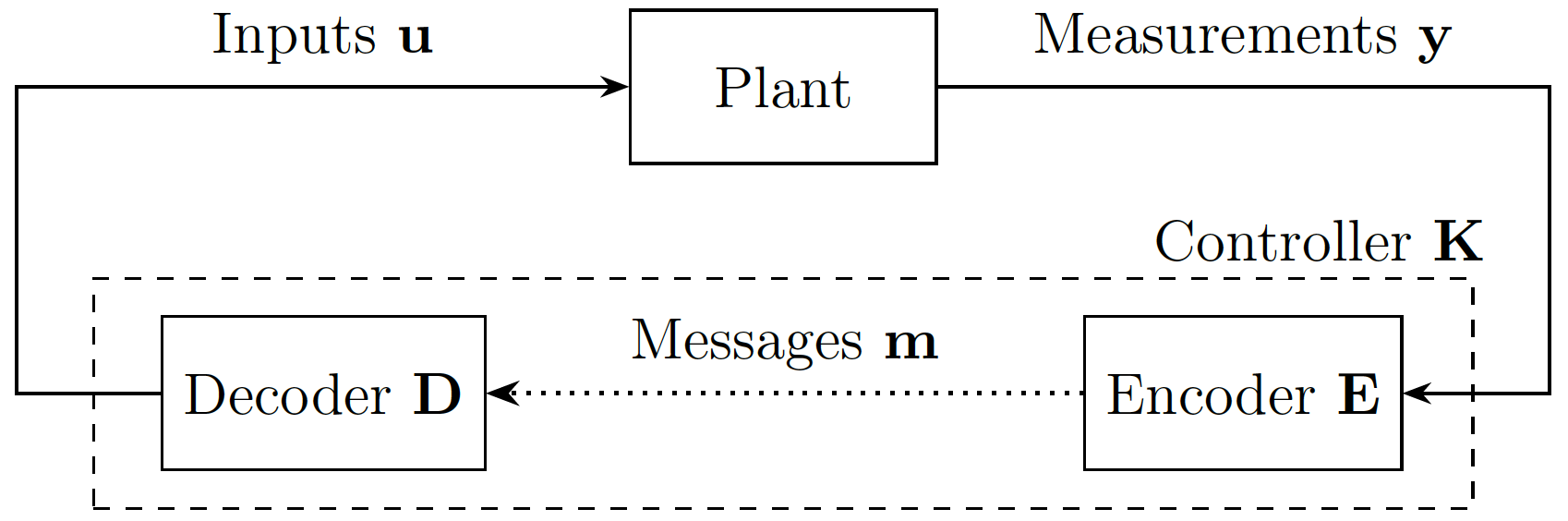
In this work, we consider a linear discrete-time control system
\[\begin{aligned} x_{t+1} &= A x_t + B u_t + w_t,\\ y_t &= C x_t + v_t, \end{aligned}\]where \(x_t\), \(u_t\), \(w_t\), \(y_t\), and \(v_t\) are the state, actuation, process noise, sensor measurement, and measurement noise, respectively. A finite horizon \(t=0,\dots,T\) is considered.
We consider a linear output-feedback controller with memory, i.e.,
\[u_t=\sum_{\tau\le t}K_{(t,\tau)}y_\tau,\]where the time-varying gains \(K_{(t,\tau)}\) are design variables.
Over a finite horizon, such a controller can be represented as a block lower-triangular matrix:
\[\mathbf{u}= \begin{bmatrix} u_0\\ u_1\\ \vdots\\ u_T \end{bmatrix}, \qquad \mathbf{y}= \begin{bmatrix} y_0\\ y_1\\ \vdots\\ y_T \end{bmatrix}, \qquad \mathbf{K}= \begin{bmatrix} K_{(0,0)} & & &\\ K_{(1,0)} & K_{(1,1)} & &\\ \vdots & \ddots & \ddots &\\ K_{(T,0)} & \cdots & K_{(T,T-1)} & K_{(T,T)} \end{bmatrix}.\]With these notations, the feedback law can be written compactly as
\[\mathbf{u}=\mathbf{Ky}.\]We consider arbitrary control constraints, such as safety constraints (keeping the state \(x_t\) inside a safe region against any \(\ell_1\)-bounded disturbance) or constraints on the \(\mathcal{L}_2\)-gain of the system. The following example illustrates how communication can be reduced while implementing a controller of this form.
Example. Consider a single-input single-output (SISO) system (\(u_t,y_t\in\mathbb{R}\)) over a horizon \(T=3\), with
\[\mathbf{u}= \begin{bmatrix} u_0\\ u_1\\ u_2\\ u_3 \end{bmatrix}, \qquad \mathbf{y}= \begin{bmatrix} y_0\\ y_1\\ y_2\\ y_3 \end{bmatrix}, \qquad \mathbf{K}= \begin{bmatrix} 5& & &\\ 10&0& &\\ 0&3&4&\\ 15&6&8&0 \end{bmatrix}.\]A direct implementation of \(\mathbf{u}=\mathbf{Ky}\) requires three sensor-to-actuator messages, since the last measurement \(y_3\) is never used. However, this controller can actually be implemented using only two messages by factorizing
\[\mathbf{K}=\mathbf{DE}:= \begin{bmatrix} 1&0\\ 2&0\\ 0&1\\ 3&2 \end{bmatrix} \begin{bmatrix} 5&0&0&0\\ 0&3&4&0 \end{bmatrix}.\]The measurements are first encoded using \(\mathbf{E}\) and then decoded using \(\mathbf{D}\). On the sensor side, the messages
\[m_1=5y_0,\qquad m_2=3y_1+4y_2\]are transmitted at times \(t=0\) and \(t=2\), respectively. The actuator reconstructs the control inputs as
\[u_0=m_1,\quad u_1=2m_1,\quad u_2=m_2,\quad u_3=3m_1+2m_2.\]The implementation remains causal: each message is transmitted only after the corresponding measurements are available, and before it is needed by the actuator. This reduces the number of communications from three to two.
In this research, we developed a general framework to design controllers requiring a minimum number of sensor-to-actuator communications. The main challenges and our solutions are summarized below.
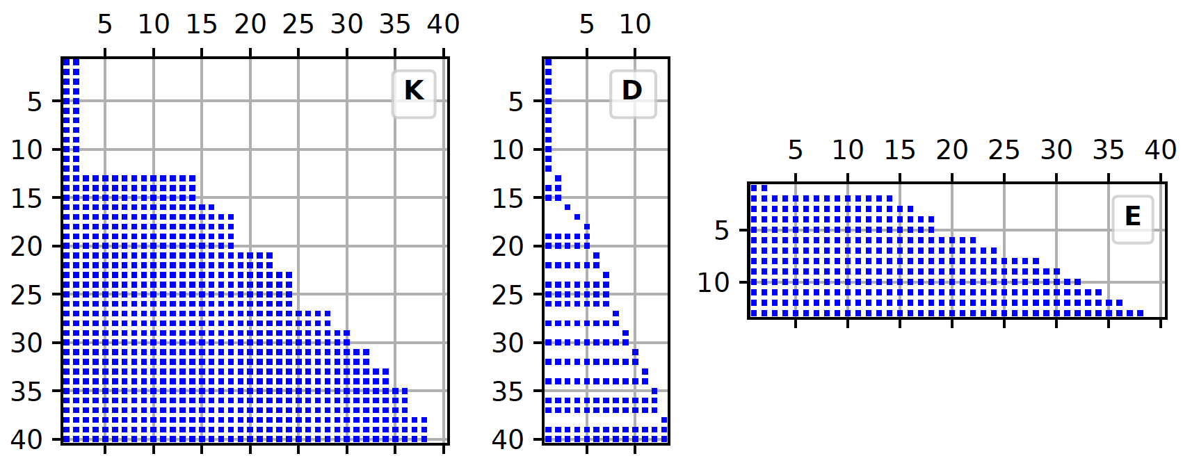
- Challenge: Find a matrix factorization \(\mathbf{K=DE}\) such that (i) the controller is preserved, (ii) the encoder \(\mathbf{E}\) and decoder \(\mathbf{D}\) admit a causal implementation, and (iii) the number of communicated messages is minimal. Classical matrix factorizations, such as the singular value decomposition, do not satisfy these causality constraints.
Solution: We show that the rank of the controller matrix \(\mathbf{K}\) exactly equals the minimum number of sensor-to-actuator messages required to implement the controller. Moreover, we introduce a new matrix decomposition, called the causal factorization, which constructs the encoder and decoder matrices directly. Consequently, minimizing communications reduces to two steps: (i) minimize the rank of \(\mathbf{K}\) under the control constraints, and (ii) compute its causal factorization \(\mathbf{K=DE}\).
- Challenge: Most control specifications are not convex in the controller matrix \(\mathbf{K}\). Although the Youla parameterization transforms these constraints into convex ones, it is not obvious how the communication objective translates under this change of variables.
Solution: We prove that the rank of the controller matrix is exactly equal to the rank of the corresponding Youla parameter. This makes it possible to design low-communication controllers through rank minimization over a convex feasible set. Since rank minimization is NP-hard, we solve a convex relaxation of the problem instead.